UML
Summary #
The Unified Modeling Language (UML) is a family of graphical notations, backed by single , that help in describing software systems, particularly software systems built using the object-oriented (OO) style.
For Visual communication for understanding to get rough idea or birds eye view.
Books #
Types of Diagrams #
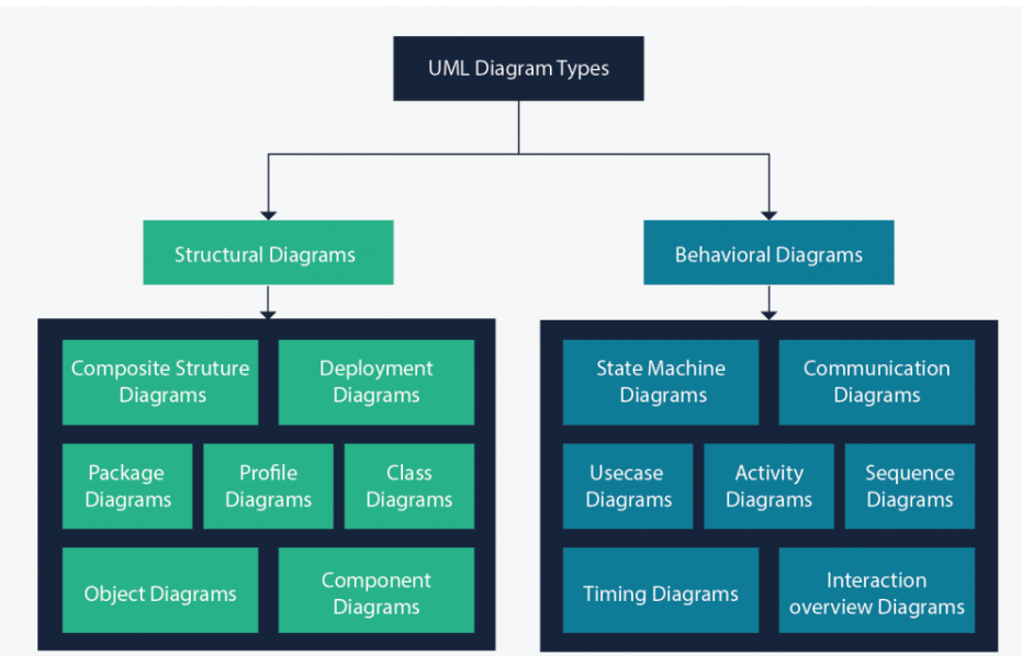
UML Structural Diagrams #
Class Diagram #
Class diagrams are the main building block of any object-oriented solution. It shows the classes in a system, attributes, and operations of each class and the relationship between each class.
Component Diagram #
A component diagram displays the structural relationship of components of a software system.
Deployment Diagram #
ref Deployment diagrams are used to visualize the hardware processors/ nodes/ devices of a system, the links of communication between them and the placement of software files on that hardware.
In UML, deployment diagrams model the physical architecture of a system. Deployment diagrams show the relationships between the software and hardware components in the system and the physical distribution of the processing.
- From IBM
Object Diagram #
Also known as instance diagram. Like class diagram but with instances of classes with data. They show how a system will look at a given time.
Package Diagram #
Dependencies between packages.
Profile Diagram #
Composite Structure Diagram #
To show internal strucutre of a class.
UML Behavioral Diagrams #
Use Case Diagram #
Gives a graphic overview of the actors involved in a system, different functions needed by those actors and how these different functions interact.
When to use them
- Representing the goals of system-user interactions
- Defining and organizing functional requirements in a system
- Specifying the context and requirements of a system
- Modeling the basic flow of events in a use case
Activity Diagram #
Activity diagrams represent *workflows in a graphical way.
When to use it
- Demonstrate the logic of an algorithm.
- Describe the steps performed in a UML use case.
- Illustrate a business process or workflow between users and the system.
- Simplify and improve any process by clarifying complicated use cases.
- Model software architecture elements, such as method, function, and operation.
State Machine Diagram #
State machine diagrams are similar to activity diagrams, although notations and usage change a bit. They are sometimes known as state diagrams or state chart diagrams as well. These are very useful to describe the behavior of objects that act differently according to the state they are in at the moment.
Sequence Diagram #
Show how objects interact with each other and the order those interactions occur. It’s important to note that they show the interactions for a particular scenario.
When to use them
- Represent the details of a UML use case.
- Model the logic of a sophisticated procedure, function, or operation.
- See how objects and components interact with each other to complete a process.
- Plan and understand the detailed functionality of an existing or future scenario.
Communication Diagram #
Communication diagrams are similar to sequence diagrams, but the focus is on messages passed between objects. The same information can be represented using a sequence diagram and different objects.
Interaction Overview Diagram #
Timing Diagram #
Examples #
Example with description of each type of diagram https://tallyfy.com/uml-diagram/